- Home
- FAQ
FAQ
Defining the CDU
A Cooling Distribution Unit (CDU) is an indispensable core component in liquid cooling systems. It is responsible for uniformly distributing the cooling medium to every heat dissipation point throughout the system. By regulating and controlling the flow and temperature of the cooling medium, the CDU ensures that all components operate stably within a safe temperature range.

The Role of a CDU in the System
The CDU works in coordination with internal pumps, heat exchangers, radiators, and controllers to form a complete cooling loop. Its primary functions include stabilizing the flow rate of the cooling medium and reducing the load on other components, which effectively enhances overall system performance and service life.
Key Industry Applications
- Data Centers & Cloud Computing: Driven by the rapid growth of AI, data centers are moving toward high-density and high-power architectures. For the latest GPUs (such as H100 and B200), traditional air cooling is no longer sufficient. In AI high-density server racks, the CDU acts as the heart of the liquid cooling system, efficiently transferring heat from the Secondary Loop (server side) to the Primary Loop (facility side). This significantly reduces Power Usage Effectiveness (PUE) and air conditioning loads in hyperscale data centers.
- Semiconductor Manufacturing & Testing: Temperature stability directly impacts product yield and process precision. CDUs provide high-precision temperature control for wafer processing (such as etching and developing) and Automated Test Equipment (ATE). This ensures data accuracy during the high-load testing of advanced chips.
- Supercomputers & High-Performance Computing (HPC): Systems used for climate simulation or gene sequencing require constant high-load operation and extreme heat dissipation. CDUs support Immersion Cooling by circulating cooling fluids between tanks and heat exchangers, and Direct-to-Chip cooling by removing heat directly from the processor via cold plates.
- Automotive Industry: CDUs are used in R&D for autonomous driving simulations, which require high-density server support. They also provide thermal management for battery and motor testing under extreme charging/discharging conditions to reduce thermal risks.
- Energy & Power Systems: In Energy Storage Systems (ESS), CDUs control lithium battery temperatures to prevent thermal runaway. They also provide cooling for high-power conversion equipment like inverters and variable frequency drives.
How Sealless Magnetic Drive Pumps Impact Performance
In a CDU system, the sealless magnetic drive pump is the power core driving the circulation. Its flow stability, corrosion resistance, and leak-proof design directly determine the reliability of the entire cooling system. Improper pump selection can lead to poor heat dissipation, coolant contamination, or equipment damage.
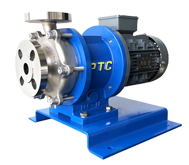
Kong Hai Enterprise FPM Series Chemical Pumps feature a sealless magnetic drive design that is corrosion-resistant and leak-proof. With a compact, high-efficiency structure that reduces volume by 1/3 while increasing delivery capacity, they are a reliable choice for 24/7 high-load liquid cooling applications.
Key Technical Indicators for CDU Selection
When evaluating a CDU system, consider the following technical specifications:
- Cooling Capacity (kW): The maximum heat load the unit can carry.
- Coolant Flow Rate (LPM / GPM): The volume of liquid delivered per unit of time.
- Inlet/Outlet Temperature Difference: A direct indicator of heat exchange efficiency.
- Operating Pressure: Ensures the safety range for piping and pumps.
- Coolant Compatibility: Material matching for water-based fluids, fluorinated fluids, or other media.
- Monitoring & Sensors: Real-time tracking of flow, temperature, and pressure anomalies.

Conclusion: Precision Starts with the Details
While overall cooling data is important, the stability of internal components—especially the circulation pump—is the true core of ensuring uninterrupted AI computing.
Kong Hai Enterprise — Providing the Best Fluid Solutions for AI Data Center Liquid Cooling
We provide tailored consulting services to meet your specific application needs. Contact us today!
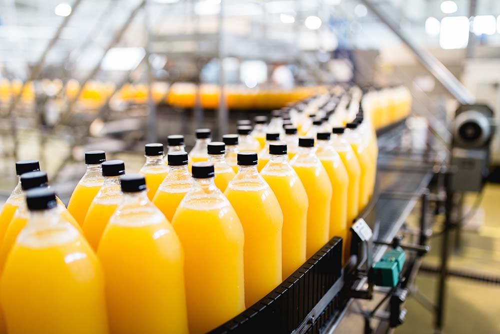
In food and beverage manufacturing processes, strict hygiene control is essential to ensure food safety and quality. High-temperature sterilization is a commonly used method in food factories to eliminate microorganisms in products or equipment through high temperatures to prevent food contamination. In this high-temperature sterilization process, the temperature and time need to be precisely controlled, along with a stable hot water delivery system. Sealless magnetic drive pumps have gained positive recognition in the food manufacturing industry due to their leak-free, high-temperature resistance and low maintenance.
In this article, we will introduce the three main types of food high-temperature sterilization and how they operate, and discuss how to choose the suitable pump for food sterilization equipment, as well as some precautions.
Types and Operating Principles of Food High-Temperature Sterilization

1. Steam Sterilization / Retort Sterilization
Steam sterilization is suitable for various pipelines and equipment, using the high temperature of saturated steam to destroy bacterial spores, making it ideal for canned foods and other long-term preservation products. However, steam sterilization equipment consumes a lot of energy and is not environmentally friendly.
- How it works: Steam at about 121°C is introduced into the pipeline or equipment, it needs to be maintained at high temperature and high pressure for a period of time to achieve complete sterilization.
- Advantages: It can kill most bacteria, enabling long-term product preservation.
- Disadvantages: High energy consumption, which may lead to increased operating costs.
2. Hot Water Sterilization (Hot Water Sterilization)
Hot Water Sterilization is used for cleaning equipment, piping, and for sterilizing food. Common sterilization methods include Pasteurization, Hot Water Shower Spray Sterilizer and Water Immersion Retort.
- How it works:
Cleaning equipment and pipelines: Using 85°C~95°C hot water, transported to the sterilization equipment through a circulating hot water pump to clean the equipment and pipelines, and effectively remove residual microorganisms and impurities in a short time. For food factories, hot water sterilization provides significant assistance in equipment maintenance and daily cleaning. - Food Product Sterilization: The packaged food is placed in a closed water spray retort, and the high-temperature water sprays on the surface of the food packaging, so that the food is evenly heated and the sterilization efficiency is improved. It is common in canned or bottled beverage sterilization operations.
- Advantages: It can achieve uniform heating of food, and at the same time avoid the problem of deformation or rupture of product packaging due to high pressure; There is no problem of large amount of exhaust like steam sterilization.
- Disadvantages: The sterilization effect is not as good as steam sterilization.
3. UHT (Ultra-high-temperature)
Sterilizing the bacteria in a short period of time with extremely high temperature, which is suitable for the mass production of milk, juice, soy milk and other foods. For example, long life milk, it can be stored at room temperature for a long period after sterilization and aseptic packaging; while fresh milk cannot be sterilized to the same degree, so it must be refrigerated throughout the process. There are different sterilization standards for different food products.
- How it works: Beverages are treated at high temperatures for a few seconds and then sealed packaging.
- Advantages: Due to the fairly short heating time, the nutrition and flavor of the food can be preserved.
- Disadvantages: Not suitable for foods containing more solid particles.

The above introduces three common sterilization methods, which basically need to be decided according to the type of food and sterilization standards. If the sterilization is incomplete, what problems will occur?
Is Sterilization Always Safe? Beware of Food Poisoning
Incomplete sterilization, which means the sterilization process is not done to an adequate degree, can lead to serious food safety issues, including:

- Consumers may get food poisoning from eating spoiled food:
Residual microorganisms will breed and multiply in food, causing food spoilage, odor, discoloration, and even toxins. When spoiled food is consumed, it will cause health hazards and may lead to food poisoning, abdominal pain, vomiting, diarrhea and other symptoms, and in severe cases, sometimes even life-threatening conditions. - Reduce the shelf life of food:
Incompletely sterilized food will greatly shorten the shelf life and is easy to spoil in a short time. - Food waste:
Spoiled food must be destroyed and scrapped, resulting in a waste of materials and costs. On the other hand, the brand image of the company will be severely damaged if there are news reports. - Legal responsibility:
Incomplete commercial sterilization of food and failure to meet basic hygiene standards are illegal acts and may face relevant legal issues.
Causes of Incomplete Commercial Food Sterilization:
- Insufficient sterilization temperature or time: The sterilization process is stopped before the food reaches the standard value of sterilization.
- Equipment problems: The equipment in the sterilization system isn't kept clean when used or lacks proper maintenance, leading to contamination and failure to meet specified sterilization conditions.
- Incomplete product sealing during packaging: Microorganisms may enter food through gaps from the outside.
For the food industry, food safety is the priority. To ensure the integrity of the sterilization process, it is crucial not only to select the appropriate sterilization method, but also to focus on the reliability of the equipment system, and proper cleaning and maintenance. These factors directly affect whether food can meet hygienic standards.
Pump Requirements in Food High-Temperature Sterilization Equipment
Why Should Food Sterilization Equipment Use Sealless Magnetic Drive Pumps?
In the hot water sterilization process, the pump used in the process from hot water transportation to the cooling system is one of the important equipment for meeting sterilization standards. Here are the specific applications of stainless steel magnetic drive pumps in equipment systems:
- Transfer hot water to sterilization equipment:
The stainless steel magnetic drive pump delivers hot water to the retort sterilizer, providing a stable flow and head that helps maintain the sterilization process's precise requirements. - Cleaning equipment and piping:
After each production batch, the parts of the storage tank and pipeline that come into contact with food should be cleaned with hot water or chemicals to keep the production line clean. Stainless steel magnetic drive pumps are used to transfer the cleaning solution to the CIP (Clean-In-Place) system. Stainless steel material has excellent corrosion resistance, which allows for transferring various acid and alkali cleaning solutions. The sealless design ensures no leakage, which can fully prevent the process from contamination. - Cooling water recycling system:
When the sterilization is completed, the used hot water will be cooled down through the heat exchanger, and the sealless magnetic drive pump will recycle it to the external cooling water system for reuse.
Key Factors in Selecting Food Sterilization Pumps
According to the above three process stages, when selecting pumps for food sterilization equipment, it is recommended to consider and evaluate these aspects:
- Heat Resistance and Stability:
The sterilization processes involve high temperatures, usually over 100°C, so the pumps used in the equipment must be able to withstand high temperatures. PTCXPUMP stainless steel magnetic drive pumps can operate at temperatures up to 280°C, with excellent stable performance even under long-term use. - No need for frequent maintenance:
Food storage tanks and piping generally need to be cleaned every day, demanding high equipment durability. Stainless steel magnetic drive pumps can be exempted from frequent maintenance, greatly reducing maintenance costs and downtime. - Ensure the purity of cooling water:
Sealless magnetic drive pumps use the magnetic coupling drive principles to form a completely sealed fluid chamber, which effectively prevents the cooling water from leaking or being contaminated and ensures its purity for subsequent recycling and reuse.
Choose the Right Equipment for Food Safety Control!
For the food manufacturing industry, the worst thing that can happen in the process is when improper equipment selection leads to substandard food hygiene and quality issues. Therefore, to make sure that food is safe to eat, it is important to select appropriate equipment and have complete sterilization procedures.
The quality of pumping equipment directly affects sterilization effect and production efficiency. PTCXPUMP metallic sealless magnetic drive pump features excellent heat resistance, no leakage, and maintenance-free characteristics, making it an ideal choice for food sterilization equipment in hot water delivery, equipment cleaning solution transfer, and cooling water recycling applications.

PTCXPUMP Metallic Magnetic Drive Pump
Highly efficient design with CE and ATEX certificates.
If you are planning to build or improve food sterilization equipment, please contact us.
Click the button below, and the PTCXPUMP expert team will provide consultation based on your application needs as soon as possible!


On the path to net-zero emissions, have you considered the impact of pump systems on energy efficiency? Sealless magnetic drive pumps, as leak-free and high-performance transport equipment, are quietly becoming a crucial driver in industrial environmental upgrades, allowing businesses to achieve sustainable development while reducing operational costs.
PTCXPUMP has been deeply rooted in the pump industry for over 40 years, actively assisting companies in building energy-efficient pump systems. How can magnetic drive pumps become an energy-saving tool for your business? Let's explore the technology and its potential applications.
A Green Future Driven by Magnetic Force
Sealless magnetic drive pumps are not only suitable for traditional industries but also play a crucial role in emerging green energy sectors. From the clean production of hydrogen energy to the efficient operation of wind power, from the safe treatment of wastewater and exhaust gases to the sustainable recycling of bioenergy, sealless magnetic drive pumps have achieved a perfect combination of "environmental protection" and "efficiency." For a deeper understanding of the applications and advantages of sealless magnetic drive pumps in various industries, you can refer to our previously published series of articles:
[ Hydrogen Energy ]
Overview: In the hydrogen electrolysis process, sealless magnetic drive pumps are required to transport the electrolyte to the electrolyzer. Since electrolytes are often chemically corrosive, leakage during transport must be prevented. In this case, sealless magnetic drive pumps made of corrosion-resistant materials are essential to ensure the continuity and stable operation of the hydrogen production process.
[ Wind Energy ]
Overview: In wind power generation systems, sealless magnetic drive pumps can be used to transport coolants and lubricating oils to the generator units, maintaining the generators within the optimal temperature range for continuous and stable operation.
[ Wastewater & Exhaust Gas Treatment ]
Overview: Scrubbing towers require pumps to transport scrubbing liquids. The scrubbing liquid is pumped to the top of the tower and then sprayed downwards to purify waste gases. After purification, part of the liquid is pumped back into the scrubbing tower for continuous recycling, while the remainder is discharged to wastewater treatment plants. Since the scrubbing liquid is corrosive, corrosion-resistant pumps are essential. Sealless magnetic drive pumps are particularly suitable for this application, effectively preventing dangerous leaks of chemical liquids.
[ Biofuel ]
Overview: In the process of converting biomass feedstock into liquid fuel, stainless steel magnetic drive pumps are responsible for transporting biodiesel or bioethanol. These pumps effectively handle solid particles and impurities in biofuels, while the stainless steel material ensures the purity of the product.
[ Hydrogen Fuel Cells ]
Overview: In fuel cell equipment, well-designed cooling and heat recovery systems are necessary. The cooling system requires circulating coolant to remove waste heat. For coolant circulation pumps, sealless magnetic drive pumps are suitable as they can prevent coolant leakage and subsequent losses.

Key Features of Sealless Magnetic Drive Pumps
For an understanding of how sealless magnetic drive pumps operate, refer to this article: What's a Sealless Magnetic Drive Pump & How Does It Work?—Read now
After gaining a basic understanding of how magnetic pumps work, let's analyze the three main features of sealless magnetic drive pumps and how they can help your industry achieve energy-saving and carbon reduction goals.
- Leak-free design:
Without mechanical seals, magnetic drive pumps can eliminate the risk of fluid leakage, reducing environmental pollution from chemicals while protecting operator safety. This significantly reduces the environmental burden in chemical processes, adhering to green technology principles. - High energy efficiency:
Our sealless magnetic drive pumps offer special energy-saving designs, which can significantly save energy consumption and electricity bills. By correctly configuring and using magnetic pumps, these pumps can greatly reduce energy consumption, improve production efficiency, and meet corporate energy efficiency standards. - Durability and low maintenance requirements:
The sealless design avoids mechanical wear, significantly reducing maintenance frequency and further extending the pump's lifespan. With fewer part replacements needed, this reduces the product’s carbon footprint, minimizing resource waste from equipment repairs and replacements.

How Sealless Magnetic Drive Pumps Help Companies Achieve Net Zero Goals
Improving equipment efficiency is one of the key strategies in achieving emission reduction targets. The design of sealless magnetic drive pumps allows for highly efficient operation and significant carbon footprint reduction, making them a powerful energy-saving tool for businesses. Sealless magnetic drive pumps are used in a wide range of applications. Beyond the aforementioned green industries, they also play a crucial role in promoting environmental protection in sectors such as chemical, semiconductor, and food and pharmaceutical industries. In terms of carbon reduction efforts in these industries, process improvements can incorporate energy-efficient equipment to enhance process efficiency. At the same time, adopting sealless magnetic drive pumps can meet the requirements for high-performance and pollution-free processes.
Additionally, as global organizations accelerate their efforts to achieve "Net Zero by 2050," the application of sealless magnetic drive pumps continues to expand. Companies adopting high-efficiency equipment not only contribute to meeting international energy management standards but also, in the long run, strike a balance between production efficiency and environmental benefits.

PTCXPUMP Metallic Magnetic Drive Pump
Highly efficient design with CE and ATEX certificates.

PTCXPUMP Thermoplastic Magnetic Drive Pump
Sealless structure, magnetic drive, no leakage concerns
Customized Energy-Saving Solutions: PTCXPUMP Responds to the Green Movement
As a leading brand in sealless magnetic drive pumps, PTCXPUMP offers not only standardized pumps but also customized energy-saving solutions tailored to the specific needs of our clients, creating the most suitable pump systems. In response to the global call for green transformation, PTCXPUMP provides comprehensive customized energy-saving solutions:
- System Optimization: Through a comprehensive assessment of the client's pump system, we provide recommendations for improving energy efficiency. These may include replacing outdated pumps, selecting appropriate pump models, and optimizing pump structure design.
- Energy-Saving Design: Our pumps utilize specialized energy-efficient design that can significantly reduce energy consumption and electricity costs.
- Premium Materials: We use materials such as GFR-PP, CFR-ETFE, stainless steel, and special alloys. These materials effectively resist corrosion from chemical fluids and maintain stable operation over extended periods. This approach reduces maintenance time and costs, thereby improving production efficiency.
- Interchangeable Parts: Key parts in pumps of different sizes are designed with a modular, streamlined approach. This not only enhances component interchangeability but also brings multiple environmental benefits:
- Reduction in raw material usage
- Decrease in waste generation
- Significant lowering of spare parts procurement costs
- Simplification of maintenance processes, controlling operational costs
- Operational Monitoring: We install dry-run protectors to monitor the pump system's status. When abnormal current or power is detected, it automatically protects the pump from running dry, preventing damage to internal components.

Dry Run Protector
Ensure smooth and stable pump operation.
Through these innovative measures, not only can you reduce the environmental impact, but you can also demonstrate your corporate social responsibility while driving carbon reduction efforts. This, in turn, enhances your competitiveness in the international market.

PTCXPUMP's sealless magnetic drive pumps are available in a variety of specifications, head, and flow rates to meet the specific requirements of various application fields.
If your industry is moving towards green technology development and you want to learn more about the energy-saving design of PTCXPUMP sealless magnetic drive pumps, click the button below now. PTCXPUMP's expert team will provide you with consultation services as soon as possible!


In our previous article "Top 5 Benefits of Using Metallic Magnetic Drive Pumps in Hydrogen Stations", we explored the advantages of hydrogen vehicles and the importance of hydrogen refueling stations. Today, we'll take a closer look at the core of hydrogen vehicles - fuel cells. How do fuel cells convert hydrogen into power? What makes them special in terms of environmental protection and efficiency?
By uncovering the answers to these questions, we'll provide a comprehensive understanding of how fuel cells lay the foundation for the future of hydrogen vehicles and identify the key equipment needed for a safe and efficient fuel cell production system.
What is a Fuel Cell?
A fuel cell is an energy conversion device that generates electricity through a chemical reaction between hydrogen (or other fuels) and oxygen. It directly converts chemical energy into electrical energy with an efficiency of over 60%.
The main difference between fuel cells and traditional batteries is that traditional batteries store energy internally and need replacement or recharging after use. Fuel cells, on the other hand, require a continuous supply of fuel (commonly hydrogen) and an oxidizer (commonly oxygen). As long as fuel and oxidizer are continuously supplied, fuel cells can continue to generate electricity as a power source for various equipment.
How do Fuel Cells Work?
The working principle of a fuel cell is actually the reverse reaction of water electrolysis. First, we need to understand what water electrolysis is.
Reaction of Water Electrolysis: When an electric current passes through water, it decomposes into hydrogen and oxygen.
💧Water + Electricity = Hydrogen + Oxygen

Reverse Reaction of Water Electrolysis: This is the opposite of the above formula, mixing hydrogen and oxygen. When hydrogen and oxygen are introduced into the two electrodes of a fuel cell, oxygen combines with hydrogen ions to form water. The electrons produced in this process create a current in the external circuit, thus generating electricity.
💭Hydrogen + Oxygen = Water + Electricity

From the above formulas and diagrams, we can see that the only byproduct of fuel cell power generation is water, which does not cause any environmental pollution. Traditional combustion methods produce harmful waste like carbon dioxide, leading to air pollution problems, which can be solved by replacing them with fuel cells. As the demand for reducing carbon emissions grows, the importance of fuel cell applications is also increasing.
Types of Fuel Cells
After understanding the concept of fuel cell power generation, it's important to note that there are many types of fuel cells, each designed for specific application needs. The most common types include Proton Exchange Membrane Fuel Cells (PEMFC), Alkaline Fuel Cells (AFC), Phosphoric Acid Fuel Cells (PAFC), Molten Carbonate Fuel Cells (MCFC), and Solid Oxide Fuel Cells (SOFC).
Proton Exchange Membrane Fuel Cells (PEMFC) are the most widely used power generation systems for hydrogen vehicles. Here's how it works.
Proton Exchange Membrane Fuel Cell (PEMFC) Working Principle Diagram:

This type of fuel cell uses a proton exchange membrane as the electrolyte and operates at low temperatures (about 60-80°C). It features quick start-up, simple design, and adaptability, making it widely used in hydrogen vehicles, portable power generation devices, and household power generation equipment.
Sealless Magnetic Drive Pumps for Hydrogen Fuel Cells
During the process of generating current and water, fuel cells also produce heat. However, if the temperature of the fuel cell stack is too high, it will affect its operational efficiency. Therefore, a complete fuel cell system must have an efficient cooling system and heat recovery system to maintain a stable temperature range for the fuel cell stack.
In the cooling system, there is a flowing coolant to take away the waste heat, which needs to be safely pumped to circulate the coolant. For coolant circulation pumps, the PTCXPUMP Metallic Magnetic Drive Pump is ideal. Its leak-free design prevents coolant loss, and it offers high flow and high head specifications, making it the best pump for cooling systems.
PTCXPUMP Metallic Sealless Magnetic Drive Pump
Sealless structure, magnetic drive, no leakage concerns
The Power Generation Core of Hydrogen Vehicles: Fuel Cells
Fuel cells are the core power generation devices in hydrogen vehicle systems. Fuel cells can stably output electrical energy, ensuring the vehicle's range. Compared to traditional internal combustion engine vehicles, hydrogen fuel cell vehicles have zero exhaust emissions and higher operational efficiency, making them more environmentally friendly. The application of fuel cells is a significant contributor to achieving the zero-emission goal of hydrogen vehicles.
Advantages of Hydrogen Fuel Cells
- Instant Power Generation: Hydrogen fuel cells can generate electricity instantly as long as fuel (hydrogen and oxygen) is available, without the need for pre-charging like batteries.
- High Energy Density: Fuel cells have high energy density, providing more energy in a relatively small space.
- Environmental Friendly and Zero Pollution: Hydrogen fuel cells only emit water during operation, and are almost close to silent operation, producing no air or noise pollution, aligning with global energy-saving and carbon reduction trends.
Versatility and Prospects of Fuel Cell Applications
Besides their well-known application in hydrogen vehicles, fuel cells have various other common applications:
- Transportation: Buses, trains, ships, submarines, etc.
- Space Devices: Compared to traditional batteries, fuel cells provide higher energy density and produce drinkable water for astronauts, making them suitable for efficient resource use in space shuttles and stations with limited space.
- Backup Power: Fuel cells can serve as backup power sources for communication base stations, data centers, etc., providing immediate power backup in emergencies.
- Distributed Power: Fuel cells can be applied in disaster prevention microgrids in remote areas, energy storage systems for community housing, or in facilities such as traffic signals.
Currently, fuel cell technology for hydrogen fuel cell vehicles and other large-scale power generation equipment is gradually maturing. Commercial production indicates growing demand, and the future popularization of new energy is expected to improve air pollution and greenhouse effect issues.
Looking for a Sealless Magnetic Drive Pump Solution?
Choose the right sealless magnetic drive pump to make your system more efficient and safer!
- Eliminate leakage risk, and prevent coolant loss.
- Durable design, long service life, reduced maintenance costs.
- High-efficiency operation, energy cost savings.
- Smooth operation, low noise, no interference with the surrounding environment.
- Customization services available to precisely match your specific needs.

To learn more, click the button below now!Kung Hai expert team will assist you as soon as possible!
▌Read More: Top 5 Benefits of Using Metallic Magnetic Drive Pumps in Hydrogen Stations
E-fuel Production Application for Stainless Steel Magnetic Drive Pump
Application of Hydrogen Energy and Applicable Pumps

Beware of the Hidden Killers in Your Pump Systems
Did you know that your pump system might be wasting resources, increasing costs, and even harboring potential safety risks?
In this article, we'll share the five key benefits of metallic magnetic drive pumps, helping you understand how this technology can transform your operations and bring real benefits to your enterprise. Whether you're in the chemical, semiconductor, pharmaceutical, wastewater treatment, or energy industry, metallic magnetic drive pumps are an indispensable part of your equipment.
What Problems Do Mechanical Seal Pumps Face Besides Leakage?
In modern industrial processes, pump systems play a crucial role in transporting various liquids. However, traditional mechanical seal pumps often face numerous challenges in practical applications. Firstly, leakage has always been a major concern in the industry. Inevitably, the wear of mechanical seals gradually reduces sealing effectiveness over time, leading to leakages. This not only results in material loss but can also pose safety hazards and environmental pollution risks.
Moreover, frequent maintenance is another issue, typically requiring periodic shutdowns for inspection and part replacement. High maintenance demands increase operational costs, including labor, materials, and downtime. It also affects production continuity, reducing overall efficiency. Especially in 24/7 operating factories, each shutdown can result in significant financial losses.
Looking for a Solution? Most Manufacturers Are Using Sealless Magnetic Drive Pumps
When transporting corrosive acidic or alkaline chemicals, the aforementioned problems require even more careful handling. In the event of a leak, it will not only cause economic losses of expensive chemicals but also may lead to safety incidents and environmental pollution. Therefore, in these high-risk industries, the requirements for pump performance are more stringent, necessitating a safe, reliable, and cost-effective solution.
Faced with these challenges, sealless magnetic pumps can overcome the annoying leakage problem. Compared with mechanical seal pumps, sealless magnetic drive pumps have advantages in maintenance costs and time. This is why most chemical fluid transfer pumps have been changed from mechanical shaft seals to sealless ones.

5 Advantages of PTCXPUMP Metallic Magnetic Drive Pumps
- Eliminate leakage risk, enhance workplace safety
- Corrosion-resistant materials for transporting chemical solutions.
- Long service life, reduced maintenance expenses
- High-efficiency operation and energy cost savings
- Customized solutions that precisely match your application needs
Advantage 1: Eliminate Leakage Risk, Enhance Workplace Safety
The sealless structure fundamentally eliminates leakage concerns, ensuring operational safety and reliability. Metallic magnetic drive pumps are particularly suitable for transporting high-risk chemicals and corrosive solutions. They not only reduce environmental pollution risks but also eliminate potential hazards to operators.
Advantage 2: Corrosion-Resistant Materials For Transporting Chemical Solutions
PTCXPUMP metallic magnetic drive pumps utilize top-grade corrosion-resistant materials, capable of steadily transporting various acid-base fluids and solvent chemicals, eliminating concerns about pump component damage due to corrosion. With metal magnetic pumps, you can confidently handle chemicals without worrying about corrosion issues, focusing instead on improving production efficiency and product quality.
Advantage 3: Long Service Life, Reduced Maintenance Expenses
In mechanical seal pumps, sealing components wear out over time and require regular replacement. In contrast, sealless magnetic drive pumps are designed for durability, significantly reducing repair frequency and component replacement needs, effectively extending their service life. Quick and easy installation reduces maintenance time and costs, ensuring your equipment can run smoothly for extended periods, thereby lowering overall operational costs.
Advantage 4: High-Efficiency Operation and Energy Cost Savings
PTCXPUMP magnetic drive pumps are designed to operate efficiently and reliably, besides improving work efficiency, they also save substantial energy consumption. This allows your equipment system to meet production needs while achieving immediate energy-saving effects, significantly reducing electricity expenses.
Advantage 5: Customized Solutions That Precisely Matching Your Application Needs
We understand that each industry and every client's needs are unique. Based on your specific requirements, we offer customized sealless magnetic drive pump designs to meet your application environment. For instance, in semiconductor processes, our metallic magnetic drive pumps provide stable delivery of chemicals, meeting the strict high-purity requirements of process environments and ensuring the yield of precision products.
In addition, if your industry is moving towards green technology, our PTCXPUMP metallic magnetic drive pumps can be paired with special energy-saving designs to help you realize your eco-friendly vision while achieving cost-saving goals, delivering dual benefits.
PTCXPUMP metallic sealless magnetic drive pumps are available in a wide range of specifications, head, and flow rates to meet the special needs of different applications.

Metallic Magnetic Drive Pumps: A Critical Step Towards Green Manufacturing
Are you seeking a solution that can give your enterprise a decisive edge in today's competitive industries? Our metallic magnetic drive pumps could be your ace in the hole! Through innovative technological design, these pumps not only significantly enhance production efficiency but you can also expect to bring long-term economic benefits for your business.
With increasing emphasis on energy efficiency and environmental protection, the application of sealless magnetic drive pumps continues to expand in the global market. In industries where operational efficiency and environmental safety are paramount—such as chemical, petroleum, natural gas, semiconductor, hydrogen energy, pharmaceutical and other fields—magnetic drive pumps have become the preferred equipment for transporting acidic and alkaline solutions.
This trend reflects the urgent need for global industry for safer and more efficient equipment, as well as the corporate responsibility to practice sustainable development and environmental protection.
Choose PTCXPUMP Metallic Magnetic Drive Pumps and Gain Numerous Advantages:
- Superior Performance
- High Operational Efficiency
- Low Maintenance Costs
- Process Safety and Reliability
- Showcase Your Company's Commitment to Environmental Sustainability
To learn more, click the button below now! PTCXPUMP expert team will assist you as soon as possible!
▌Read More:What are the considerations when choosing a pump?
What's A Sealless Magnetic Drive Pump & How Does It Work?
The Material Difference and Selection of Sealless Magnetic Drive Pumps

How Can Liquid Cooling Solutions Bring a New Revolution In Cooling for AI Technology?
The innovative application of artificial intelligence (AI) technology is bringing disruptive changes to various fields and creating new possibilities for operating models and development prospects. The powerful processing power required behind the rapidly growing AI wave also poses new challenges to the cooling requirements of servers.
As the demand for the application of AI technology increases significantly, data centers must process more data at a faster speed, thus driving the transformation of cooling architecture. Traditional air cooling systems (such as fans or refrigerated air conditioners) can no longer cope with the huge heat generated by high-density computing. Liquid-cooled server racks have emerged in recent years and become an innovative solution for this problem.
When the server is performing deep learning and data analysis, the extremely large amount of data and complex processes will generate huge amounts of heat. The liquid cooling system can quickly and effectively remove this heat to ensure that the server can maintain stable operation. The emergence of liquid-cooled server cabinets provides strong support for the development of AI technology; as AI becomes a trending topic this year, "immersion cooling" has attracted widespread attention for its excellent heat dissipation performance, which also means that liquid-cooled server cabinets are leading us to welcome the first year of liquid cooling.
Cooling Challenges For AI Servers in The Face of Increasing Processing Demands
The importance of server cooling for equipment stability
When we use computers or mobile phones, we often feel heat. That is because the central processing unit (CPU) and other electronic parts inside the device generate heat when working. If this waste heat cannot be effectively discharged, it will affect the performance and life of electronic components. In particular, AI servers have stronger processing power and larger storage space than ordinary servers and generate relatively more heat. To ensure that AI servers can continue to provide high computing power, these large-scale AI data centers must use effective heat dissipation architecture to cool down the chips.

Limitations of Traditional Air Cooling Systems: Unable To Handle The Heat of Intensive Workloads
At this stage, the traditional air-cooling system is still the most common cooling method in server racks. It uses air as a heat dissipation medium, blowing cold air into the heat dissipation fins through a fan, performing air circulation, and taking away the heat generated by the server by heat convection. However, the heat dissipation effect of traditional air cooling is limited.
1. Limited heat dissipation capacity
Air is a medium with poor heat conductivity and can only absorb limited heat. Once it reaches saturation, its heat dissipation efficiency will be limited. Especially in high density server racks, where a large number of servers are placed in a limited space, overheating issues are more likely to occur.
2. Noisy
Because the fans need to run at high speeds to circulate enough air to cool the servers, this creates mechanical noise that can cause interference.
3. Low efficiency
If you want enough airflow to cool a large amount of heat, a large space is required. Overall, the efficiency of the traditional air-cooled system is low.
As server processing demands continue to increase, many high-specification servers have approached or exceeded the heat dissipation limit that air-cooling systems can provide. We must use liquid cooling technology to overcome the challenges of low efficiency and increased energy consumption faced by traditional air-cooled heat dissipation architecture.
Advantages of Liquid Cooling Technology and Application of Sealless Magnetic Drive Pump
Compared with traditional air cooling systems, liquid cooling technology can effectively improve heat dissipation efficiency. This is because liquid has better heat conductivity than air and can absorb and take away heat from the server more quickly, ensuring that the equipment will not malfunction due to overheat.
In the past, many data centers used air cooling, but now they use liquid cooling technology as the best solution for heat dissipation in AI servers. Liquid cooling systems usually use fluorinated liquid as the cooling medium, and the sealless magnetic drive pump circulates the coolant in the server racks.
Air Cooling vs. Liquid Cooling
| Characteristic | Air Cooling Technology | Liquid cooling Technology |
| Heat dissipation medium | Air | Liquid (water, oil, etc.) |
| Heat dissipation capacity | limited | high |
| Noise | noisy | quiet |
| Efficiency | low | high |
| Cost | low | higher |
| Complexity | Easy to install | Installation is more complicated |
Working principle and advantages of immersion cooling
Immersion cooling technology is an innovative solution that has attracted much attention in the field of data centers and High Performance Computing (HPC) in recent years. The following introduces the operating principle and advantages of immersion cooling applications.
How Does Immersion Cooling Work?
1. Basic Concept:
- Immersion cooling is a type of liquid cooling technology. Immerse servers or electronic equipment directly in non-conductive coolant to directly absorb the heat generated by the chip and take away excess waste heat, thereby optimizing server performance.
- This approach can greatly improve energy efficiency because no other cooling parts such as fans, cooling fins or heat pipes are required.
2. Single-Phase Immersion Cooling:
The server is completely immersed in the cooling tank with coolant, relying on the flow of coolant to conduct the heat energy of the chip and quickly dissipate heat for the chip. After absorbing the heat energy, the coolant whose temperature rises is then transported to the external cooling tower through the heat exchanger and then cooled down. The final coolant is transported back to the cooling tank through the pump and continues to circulate.

3. Two-Phase Immersion Cooling:
Immerse high-temperature electronic components that need to be dissipated in a cooling tank. The heat from the chips will be transferred to the coolant. As the coolant absorbs the heat, it undergoes a phase change to vapor. The vapor rises and condenses into liquid upon contacting the condenser, dripping back into the cooling bath and continuing the heat dissipation cycle. This design can more effectively reduce server temperature and improve heat dissipation efficiency. It not only relies on the flow of coolant but also uses the vaporization of the coolant to take away more waste heat.

Sealless Magnetic Drive Pump Used In Immersion Cooling Technology
In immersion cooling technology, the application of sealless magnetic drive pumps is crucial. In order to maintain efficient and stable operation of the system, the performance of the coolant circulation pump must reach high standards. Sealless magnetic drive pumps are driven by magnetic force, eliminating the need for traditional mechanical seals, eliminating the risk of liquid leakage, and improving system reliability and safety.
Learn about the efficient use of sealless magnetic drive pumps in immersion cooling systems:
1. Coolant circulation: In single-phase immersion cooling and two-phase immersion cooling systems, pumps are used to transport coolant.
- In the single-phase immersion cooling system, the external cooling tower needs to return the coolant to the cooling tank after cooling. This process requires the use of a reliable sealless magnetic drive pump for transportation to ensure the circulation of the system.
- In the two-phase immersion cooling system, after the steam condenses into liquid, part of the liquid drips directly back into the cooling tank, while the rest is driven by a pump to continuously circulate the coolant throughout the system. This ensures effective heat dissipation, maintains uniform coolant distribution, and prevents localized overheating.
2. Enhanced system stability: Since the sealless magnetic drive pump does not have a mechanical shaft, downtime and maintenance costs are reduced, thereby improving the stability and operating efficiency of the entire cooling system.
PTCXPUMP sealless magnetic drive pumps provide various specifications of heads and flow to meet the unique liquid cooling needs of different data centers.
Technological Innovation and Market Trends: The Application Potential of Immersion Cooling in AI Development
As an innovative liquid cooling technology, immersion cooling can be widely used in many industries due to its efficient heat dissipation capacity and reliability, showing huge market development potential.

What industries is immersion cooling suitable for?
- Big Data
In a big data processing environment, servers need to process huge amounts of data, and a large amount of heat will be generated in the process. Immersion cooling technology can effectively absorb and dissipate this heat, ensuring that the system can perform analysis and processing smoothly. - Artificial Intelligence (AI)
The operation and training of artificial intelligence require powerful computing power, so efficient cooling systems must be used to take away the heat generated by the servers. Immersion cooling technology can realize “Green Computing”, reduce energy consumption while improving heat dissipation efficiency, help you save operating costs, and keep AI servers stable during high-density computing. - Edge Computing
Edge computing requires a rapid and immediate response. In order to avoid delays in data transmission, edge computing and cloud computing have very high requirements for the immediacy and stability of data processing. Computing centers must use appropriate cooling equipment, and immersion cooling technology can quickly remove heat in a limited space and prevent heat accumulation, thereby improving computing efficiency and reducing latency. - Blockchain & Cryptocurrency
Blockchain technology and cryptocurrency mining require a large amount of computing resources. Computer equipment using immersion cooling technology can meet the high-performance computing and low-latency requirements of mining programs.
The Future of Liquid Cooling Technology
The rapid development of liquid cooling technology not only promotes the advancement of AI applications but also plays an important role in energy conservation and carbon reduction in global data centers. Immersion cooling systems are gradually becoming the new favorite of data centers with their high-efficiency cooling capabilities and superior energy efficiency.
Future development directions include further improving the efficiency and reliability of the cooling system, how to reduce construction costs, and promoting the application of liquid cooling technology in more emerging fields. In addition, hybrid cooling methods that combine air and liquid cooling have also received attention, combining the advantages of both systems, optimizing cooling efficiency, and meeting the special requirements of different environments.

Immersion Cooling System Uses PTCXPUMP Sealless Magnetic Drive Pump
In the immersion cooling system, the main function of the sealless magnetic drive pump is to continuously circulate the coolant to maintain the stable operation of the entire system.
1. Safe and Reliable
The design of the sealless magnetic drive pump prevents the risk of leakage. The magnetic drive design improves the operational safety and reliability of the system, especially in long-term operation and high-density settings, which can effectively reduce maintenance costs.
2. Efficient Heat Management
The magnetic drive pump can provide stable and continuous coolant circulation, effectively taking away the heat generated by servers and other electronic equipment. This cooling effect not only ensures the stability of the internal temperature of the system but also prevents heat energy from accumulating inside the cabinet, ensuring the operating efficiency and lifespan of the equipment.
3. Energy Saving and Environmental Protection
The sealless magnetic drive pump has low power consumption and operates with minimal noise, improving the comfort of the working environment. At the same time, it helps save energy and reduce carbon, helping data centers meet sustainable development requirements.
4. Economic Benefits
By using sealless magnetic drive pumps, companies can not only reduce energy costs for cooling systems but also reduce downtime and costs due to mechanical failure and maintenance. This makes magnetic drive pumps ideal for today's high-performance computing needs.

How To Save Energy On Equipment and Effectively Reduce Maintenance Costs? What You Need Is the Right Pump and A Professional Team!
PTCXPUMP helps you select the right pump, eliminating the risk of incorrect selection and cost waste. We also provide professional maintenance services to ensure the safe use of the equipment system.
With over 40 years of pump industry experience, PTCXPUMP stands as the prime choice for customers seeking reliability. Since we are familiar with the importance of industrial characteristics for pump selection, we will help you customize the most suitable pump based on pump performance, specifications, and operating conditions provided by customers. This not only improves equipment system efficiency but also reduces unnecessary energy consumption and maintenance costs.
Facing the trend of liquid cooling in the AI era, PTCXPUMP is ready to keep up with the international pace. Please feel free to contact us at any time to match a suitable magnetic pump in your AI server application to easily meet the challenges of efficient computing.

When you purchase a new fluid equipment, the manufacturer needs the user to provide a series of operating conditions. For example, when purchasing chemical pumps, you need to provide basic operating conditions such as head and capacity. Probably this is the common experience of lots of people, and it may make people feel a little troublesome, but because chemical pumps are specially designed for the special needs of the chemical industry, most of the chemicals are dangerous, so compared with the water pumps, there are of course more factors to consider before deciding on an appropriate chemical pump. There are mainly 10 things, which are items that manufacturers must confirm with customers first.
What Should Be Pumped?
First, must know what the chemical fluid to be transferred is. Since the characteristics of chemical fluids will directly affect the type and material of chemical pumps used, understanding the characteristics of chemical fluids is the most preliminary task for pump selection. The fluid properties include corrosiveness, temperature, viscosity, concentration, specific gravity and impurities.
For the relevant technical terms of the pump, there is a detailed explanation in this article: What are the considerations when choosing a pump? It can be read to understand more about this.
What Is the Amount of Fluid Will Be Pumped?
The capacity refers to the volume of fluid that the pump needs to deliver per unit time and indicates the flow rate and amount of the fluid passing through the pump during delivery. It is usually denoted by the letter Q, the unit of measurement is: LPM, m³/h or m³/s. The amount of flow will affect the size of the pump and the diameter of the piping.
How Much Is the Working Pressure?
Working pressure is the force required to move fluid through the system. If the range of working pressure is too high or too low, the expected delivery effect cannot be achieved. Therefore, it is necessary to consider whether to use a chemical pump with good pressure resistance to meet the operating range of the system.
How High Is the Maximum Head?
The height to which the fluid needs to be moved, which means the vertical height from the fluid source surface to the final outlet, in m. The density of the transported liquid, the diameter of the impeller and the number of stages of the impeller will all affect the height of the head.
What Is the Connection Type?
Regarding how to connect and fix the pump and the pipeline, flanges, unions or hoses are usually used. In the application of medium and large pumps, the flange form is often used as the main connection method. Different types of chemical pumps are also equipped with flange types of different specifications.
To get more information of flange, please refer to the following three articles about flange.
Article1: What is a Flange? What are the types of flanges?
Article2: 5 Types Commonly Used Flange Faces
Article3: Flange Standards (ANSI, JIS, DIN, GB)
What Is the Connected Motor Type?
Generally speaking, most pumps need to be connected with a motor and a power as the source of power for the pump (except for specific types of pumps, such as air-operated diaphragm pumps, etc.). When using it with a motor, you need to pay attention to whether there will be failures such as motor burnout. Depending on the application and working environment, the type and specification of the motor are also different.
More about motors: What are the considerations for motor selection?
What's the Difference between Normal Motors, Inverter Duty Motors, and Explosion-Proof Motors?
What Area Are Chemical Pumps Used In?
When chemical pumps are used in the semiconductor industry, PCB industry, medicine and food industry, etc., when cleanliness is in high demand, it is necessary to use pumps made of specific materials, such as stainless steel SUS316L; or in other special environmental conditions, such as using pumps located in coastal areas are prone to corrosion due to the extremely high salinity of seawater. Both pumps and motors require special coatings to prevent erosion by seawater or rain.
For applications such as chemical industry, semiconductor industry, wastewater treatment, energy and environmental protection, petrochemical industry, food industry, pharmaceutical industry, etc., PTCXPUMP is a reliable partner of domestic and foreign manufacturers, and can provide customized and safe magnetic drive pumps according to the operating environment.
How Often Will the Pump Be Operating?
Pumps that run continuously for long periods of time must be constructed of stronger materials to increase durability and extend their service life than pumps that are run only once in a while. When the pump is running without any fluid, it must also be ensured that dry running will not happen, otherwise the motor may burn out very quickly.
How to Protect the Pump?
To prevent pump failure, causing downtime and increasing operating costs, the pump is best used with a dry running protector. The dry running protector is used to monitor the current or power of the motor during operation. When the current is too high or too low, it will immediately issue an alarm or automatically shut down the motor. This function greatly reduces the probability of pump failure and maintenance costs. Based on safety and cost considerations, the optional dry running protector is also a machine that cannot be missed.
Should Maintenance Work be Carried Out by Myself?
To ensure the longevity and efficiency of chemical pumps, proper maintenance and care is essential. Although self-maintenance can save a little cost, entrusting it to a manufacturer with good service, the maintenance of its professionals can guarantee the maintenance of product quality and operational efficiency.
Some ways you can extend pump life: Pump Maintenance Guide
PTCXPUMP provides you with chemical sealless magnetic drive pumps, which are widely used in a wide range of applications. Contact us and provide your requirements, we will assist you in accurate selection and providing the most appropriate pump. The maintenance problems after the products are used can also be entrusted to us with peace of mind. PTCXPUMP has a warehouse and repair factory, and can help you solve any product problems with instant and perfect after-sales service.
The average annual maintenance and operating costs of the pump are higher than other types of rotating machinery. As the main force of the factory, its energy consumption accounts for one of the highest proportions among many industrial equipment. Especially in the chemical industry, because it relies on chemical pumps to transport some corrosive liquids, the time and expense spent on operation and maintenance cannot be underestimated during the entire life cycle of the chemical pumps. Therefore, how to reduce the damage rate of the chemical pump and increase its production capacity has become a common topic for all factories.
Of course, it is well-known to try our best to achieve "energy saving." However, in addition to saving energy consumption of chemical pumps, if we want to have a great effect in reducing costs and increasing factory output, we must also improve the "reliability" of pumps. In order to make the chemical pump run more smoothly, the following methods can be adopted. To save pump energy, these are the ways: 10 Tips on Energy Saving in Pumping Systems
Proper Design and Equipment
Using the proper pump is the first step in building a reliable pumping system. The specifications should meet the operation requirements. Many factors must be taken into consideration, such as flow rate, head, fluid characteristics, operating temperature and pressure, etc., and then accurately select the most suitable model according to the pump performance curve, even under dynamic operating conditions. It can also prevent the chemical pump or parts from overloading and excessive vibration to shorten the service life. How to read the Performance Curve: Easy Way to Understand the Pump Performance Curve
In addition, fatigue wear and cracked surfaces of components are the root causes of pump failures. The fatigue life of components under cyclic or dynamic loading can be programmed to be infinite. For those components that have previously broken, the design can be redeveloped to increase the expected fatigue life as the cyclic loading and associated stresses are reduced.
Operational Status Monitoring
As we often mentioned, the pump needs regular health checks, but in order to grasp its performance in a more timely and comprehensive manner, preventive maintenance must be done, and professional status monitoring tools. The purpose of continuous monitoring is to prevent failures such as process delays or downtime, and expensive repair costs.
Prevent Leakage Problem
If a chemical pump leaks when delivering fluid, it will be a hazard to the operator and the environment, and you will also have to bear the cost of cleanup and material loss. The sealless magnetic drive pump completely seals the fluid in the chamber, which can successfully avoid leakage concerns. The simple structure makes maintenance more convenient and the maintenance frequency can be reduced. In addition, its excellent corrosive fluid handling ability can help your factory to improve productivity. In terms of fluid delivery, the sealless magnetic drive pump can provide a reliable solution.
Pump Packages and Transport
The size of the wooden box for packing the pump must match the size of the product. For different pumps, the transport boxes are different. Try to avoid
damage to the pump and parts during the process of moving and transporting. If you consider environmental protection and operation, you can also replace disposable materials with reusable materials
If you want to build a reliable chemical pump system, please refer to the above four methods to improve pump performance and reliability, but it is also recommended to consult professionals in advance to achieve the desired results.
At PTCXPUMP, we offer reliable sealless magnetic drive pumps. Contact us and a professional team will work with you to help you choose the best chemical pump and increase pump capacity according to actual operating conditions!

Bearings are fixed parts required for mechanical operation, which can keep the shaft at the center and guide the gearing of other parts.
Bearings have a limited service life, and improper use or other factors will accelerate bearing damage, so regular replacement and maintenance are indispensable. If you don’t want to worry about this anymore, you can use the following 7 ways to effectively reduce the risk of damage to mechanical equipment and prolong bearing life.
- Proper Lubrication
Regular replenishment or replacement of correct, high-quality lubricants, keeping the bearings lubricated is primary, and the oil film surface can minimize the wear of the parts when they are in contact. For equipment operating at high speed, the lubricant can also take away the heat generated by the internal friction of the bearing to achieve the effect of heat dissipation and cooling. The lubricant can use oil or grease, try to choose the lubricant recommended by the original equipment manufacturer (OEM).
Of course, the lubricant also has a fixed lifespan. When the lubricant loses a certain viscosity and lubricity, it will cause churning, or the bearing will stop suddenly and cause system shutdown. Therefore, it is also necessary to pay attention to the replenishment of lubricant.

- Mount the Bearings Correctly
Since the correctness of the bearing installation directly affects the life and mechanical precision, so the correct method and special tools should be used in the process of mounting and dismounting the bearing.
After installation, it is also necessary to check the installation position, whether the radial clearance of the bearing is just right to rotate flexibly without vibration, whether the lubricant can flow into the bearing smoothly, and confirm whether there is light leakage around the bearing and the shoulder. If there is no light leakage, it means the installation is correct; if there is light leakage around the shoulder, it means that the installation is incorrect, and the bearing needs to be adjusted to make the two close.

- Prevent Pollution
Clean bearings: Bearings are precision components and should be stored horizontally in a clean, dry environment to avoid exposure to any air pollutants. Even the slightest contamination can impair performance, so keep the packaging intact and airtight until ready to use.
Clean lubricant: In addition, under long-term use, the lubricant will also contain pollutants. In order to prevent the bearing from being worn by particles, the only way to keep it clean is to replace it with new lubricant. - Appropriate Seal Type
The bearing needs to have good sealing performance. If the sealing is not good, dust particles, liquid and other pollutants will enter the bearing, resulting in wear of parts, and due to the leakage of lubricant, it will seriously cause product and environmental pollution. Choose a suitable seal type can help preventing these problems.
Whether it is temperature or lubricant, there are many factors that affect the sealing type of the bearing, mainly divided into contact seals, non-contact seals, and labyrinth seals.
- Contact seals: Also known as the lip seal, pressure is exerted on the inner ring of the bearing so that the seal and the bearing come into contact. Since it is in the form of direct contact, there is no gap between the seal and the rotating shaft, and it is easy to generate heat due to friction during rotation, so it is only suitable for medium and low speed operating environments.
- Non-contact seals: The seal is fixed on the outer ring and will not exert pressure on the bearing of the inner ring. There is no contact between the seal and the bearing parts. There is a gap between the seal and the rotating shaft, so there is no friction and wear problem under normal operating conditions, and it can also prevent overheating.
- Labyrinth seals: A more complex labyrinth seal is a bearing isolator that combines contacting and non-contacting sealing elements in one assembly. A labyrinth seal consists of a stationary and rotating part that interlocks the two, and its structure creates small tortuous gaps that make it difficult for substances to escape or penetrate the bearing. Labyrinth seals combine the advantages of contact and non-contact seals, providing the sealing capabilities of contact seals without the frictional overheating problems like non-contact seals.
However, you get what you pay for, and the price of labyrinth seals with high complexity is of course higher than other seals. Therefore, the most suitable seal type must be evaluated according to the equipment and operating environment.
- Adjust Load and Bearing Size
If the bearings do not match the load requirements, wear problems will still occur during high-speed operation, which can be solved by changing the total load of the system or using suitable bearings.
- Prevents Rust and Corrosion
Exposure to water for a long time will cause rust and corrosion, and may even fall off during operation, and affect the performance of the mechanical system, so special attention should be paid to dry storage, and gloves must be worn when handling to avoid contact with sweaty hands.

- Inspection and Maintenance
Finally, be sure to take regular maintenance and inspections, such as checking the degree of wear, cleaning the bearings with cleaning oil (gasoline, kerosene), etc., so as to ensure the best performance of the bearings and prevent any abnormal conditions of parts or equipment. This is one of the most basic ways to extend bearing life.
Pump Maintenance Points: Pump Maintenance Guide
However, an ounce of prevention is worth a pound of cure, and here comes an easier and more cost-effective way to solve the above bearing problems!
PTCXPUMP Sealless Magnetic Drive Pump that Can Be Safely Applied
In the use of the pump, in order to reduce the frequency of replacing parts as much as possible, it is recommended to use the PTCXPUMP sealless magnetic drive pump. Compared with the traditional mechanical seal pump, the sealless design can effectively avoid leakage, and there will be no fluid leakage or work safety problems. This aspect is also helpful for improving efficiency.
The bearing part is made of SiC (silicon carbide) material, which has excellent corrosion resistance and high wear resistance. The patented design of the internal flow channel of the bearing allows the fluid to pass through the interior quickly, which not only has the function of instant lubrication, but also can quickly take away the mechanical heat generated by the operation. Since the chemical fluid is not easy to remain, the problem of the pollutants mentioned above is reduced, and there is no need to replace the bearing frequently like ordinary bearings, and at the same time, the possibility of the shaft being stuck due to fluid crystallization is greatly reduced.
In addition, it is made of engineering plastic or metal, which has excellent corrosion resistance and is suitable for transporting highly corrosive liquid such as hydrochloric acid, sulfuric acid, hydrofluoric acid and acetic acid or flammable and explosive fluids.
PTCXPUMP sealless magnetic drive pump has various models to meet your various operating requirements.
Contact us and our professional team will work with you. According to the actual operating conditions, to select the best pump for you. By choosing the correct type of pump to extend the pump service life, so as to reduce production costs.
When we use the pump, in order to maintain its performance and avoid operational problems, there are some maintenance and methods of routine job that need to be understood. The following will introduce how to maintain and inspect the pump to extend the service life of the pump, in order to reduce maintenance costs.
According to the difference in initiative, the types of maintenance are mainly divided into corrective maintenance and preventive maintenance.
What is Corrective Maintenance?
Corrective maintenance: When the pump leaks, the efficiency decreases, stops or the motor failure, resulting in production loss, it is necessary to quickly purchase or install spare parts in an emergency to restore the equipment system to an operational condition.
What is Preventive Maintenance?
Preventive maintenance: Routine or regular (hourly, daily, weekly, monthly, yearly) scheduled inspections aimed at maintaining the equipment in its current state and preventing malfunction, by dismantling devices, replacing seals such as gaskets or mechanical seals, and checking the pump's external and internal parts for wear.
In addition to the necessary to ensure that the pump can operate normally after started through some inspection steps, carrying out the routine preventive maintenance through the following checklists is also a point of pump protection.
Routine inspection:
1. Check the pump body, connection plate and base plate are corroded or damaged.
2. Check whether there is leakage between the pump and the piping.
3. Whether the surface of the motor is damaged or corroded.
4. Whether the pump is operating normally, and check there is any abnormal noise or vibration.
5. Confirm the flow and pressure at the pump inlet.
6. Confirm the flow and pressure at the pump outlet.
7. Confirm the liquid height in the tank.
8. Whether the motor current value is within the rated range.
If there are spare parts, it is also necessary to test run frequently and check whether they can work normally.
Regular inspection:
(depending on the usage conditions and hours, about once every 3 to 6 months)
1. Front casing, rear casing
Check for cracks, abnormal wear, crystallization, or foreign matter attached.
2. Gasket
Check for deformation, corrosion, or swelling.
3. Impeller and inner magnet
Check for scratches or cracks, crack or crystallization on bearings, bearing wear or tear, deformation of the impeller, etc.
4. Shaft
Check for scratches or cracks.
5. Rear casing
Check for corrosion, cracks, holes and scratches.
In addition to the above-mentioned maintenance and detection methods, preventive maintenance also includes the use of monitoring technology to determine the current operating status of system equipment. In order to correct the pump problem before it occurs, the current or power of the pump motor can be monitored by using PTCXPUMP dry run protector. When the current is too high or too low, an immediate warning or automatic shutdown will be issued, which greatly reduces the pump failure probability and maintenance costs.
Considering preventive maintenance, PTCXPUMP sealless magnetic drive pump can reduce the cost of preventive and corrective maintenance because of its simple structure and high durability.
Best Solution For Chemical Transfer – PTCXPUMP Sealless Magnetic Drive Pump
Speaking of flanges, in addition to connecting or closing the pipes, when installing pumps, flange is significant for connected with pipe. After understanding the basic types of flanges and flange faces, the flange standard specification, its resistance pressure capacity, the flange thickness, and applicable countries, also need to be paid attention when selecting.
What are the standards of flanges?
The common flange standards are ANSI, DIN, JIS, GB.
ANSI is most commonly specified in the United States.
DIN is usually specified in Europe.
JIS specifies the standards used for industrial activities in Japan.
GB is the national standard of People's Republic of China.
The international flange standards are mainly use ANSI and DIN, but the flange connection dimensions of these two standards are completely different and unable to exchange.
1. ANSI
Pressure Ratings: 150 LB, 300 LB, 400 LB, 600 LB, 900 LB, 1500 LB, 2500 LB
Flange Types: slip on flange, welding neck flange, threaded flange, lap joint flange, socket weld flange, blind flange
Flange Faces: flat face, raised face, ring type joint, male and female, tongue and groove
2. DIN
Pressure Ratings: PN6, PN10, PN16, PN25, PN40, PN64, PN100, PN160, PN250, PN320, PN400
Flange Types: slip on flange, welding neck flange, threaded flange, lap joint flange, blind flange
Flange Faces: raised face, ring type joint, male and female, tongue and groove
3. JIS
Pressure Ratings: 5K, 10K, 16K, 20K, 30K, 40K, 63K ( 'K' is the unit of pressure rating used in Japan.)
Flange Types: slip on flange, welding neck flange, threaded flange, lap joint flange, socket weld flange, blind flange
Flange Faces: flat face, male and female, tongue and groove
4. GB
Pressure Ratings: 〔series 1〕PN1.0, PN1.6, PN2.0, PN5.0, PN10.0, PN15.0, PN25.0, PN42.0
〔series 2〕PN0.25, PN0.6, PN2.5, PN4.0
DIN: PN0.25, PN0.6, PN1.0, PN1.6, PN2.5, PN4.0
Flange Types: slip on flange, welding neck flange, threaded flange, lap joint flange, blind flange
Flange Faces: flat face, raised face, male and female, tongue and groove
ANSI: PN 2.0, PN 5.0, PN 10.0, PN 15.0, PN 25.0, PN 42.0
Flange Types: slip on flange, welding neck flange, threaded flange, lap joint flange, socket weld flange, blind flange
Flange Faces: flat face, raised face, ring type joint, male and female, tongue and groove
The above are the basic flange standards. When considering the flange to be installed with the pump, it is recommended to consult with professionals before selecting.
PTCXPUMP sealless magnetic drive pump provides standard flange specifications(ANSI,JIS,DIN) for easy pipeline connection. It can adjust screw hole position to avoid leakage of inlet and outlet.
Best Solution For Chemical Transfer – PTCXPUMP Sealless Magnetic Drive Pump
Flanges play an important role in connecting pipes, besides knowing the basic types of flanges, it is necessary to further understand the form and application of flange faces. In addition, since the specifications of flanges are very diverse, the standard classification of flanges also needs to be paid attention to when selecting them. The common flange standards will be introduced in the next article.
What are the commonly used flange faces?
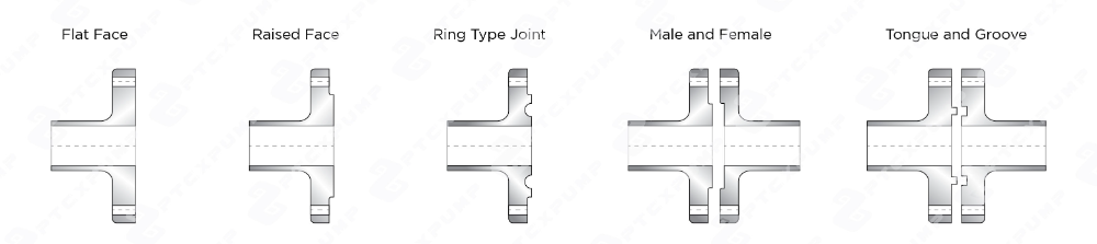
1. Flat Face (FF): The smooth surface and simple structure make it easy to process the corrosion-resistant lining. Using full-face gasket to cover the entire flange sealing surface. Due to the large contact area between the sealing surface and the gasket, after pre-tightening, the gasket is easily moved to both sides and be squeezed out of the sealing surface. It is well suited to low pressure and low temperature applications. Flange gaskets are generally divided into metal gaskets and non-metal gaskets, flat face flanges use non-asbestos gaskets.
2. Raised Face (RF): The smooth surface and simple structure make it easy to process. Because of its easy installation, it is the most widely used type of flange employed in the oil and gas and chemical engineering industries. The contact surface of the gasket protrudes from the bolting circle face, concentrating the pressure on a smaller gasket area, thereby increasing the pressure containment capability. Applicable gasket materials include non-metallic flat-ring gaskets and metallic spiral wound gaskets and metal jacketed gaskets.
3. Ring Type Joint (RTJ): The metal ring is placed in the groove, and the gasket will not be pressed into the groove. The compression area is small, and the pressure of the gasket is uniform. When the bolt is tightened, the metal ring is compressed to form a tight seal. Because the gasket and the medium are not in direct contact, it can be used in applications with strict sealing requirements, such as high temperature and high pressure, flammable, explosive and toxic media. Ring type joint flanges use oval ring gaskets or octagonal ring gaskets.
4. Male and Female (MFM): It consists of a male face and a female face, which are used in pairs and are easy to align during installation. Placing the gasket on the female face can prevent the gasket from being extruded, so it can be used in applications with high pressure and strict sealing requirements, but it is not easy to replace the gasket. However, the gasket may still be squeezed out when the male and female flanges are used under high temperature operating conditions. Applicable gasket materials include non-metallic flat gaskets, metallic spiral wound gaskets and metal jacketed gaskets.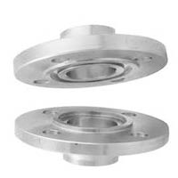
5. Tongue and Groove (TG): It consists of a tongue flange and a groove flange, which are used in pairs. The tongue flange is manufactured with a raised ring that is machined into its face, and the groove flange is produced with a matching depression machined onto its face. Placing the gasket in the groove flange, so the compression area is small, the gasket is uniformly stressed, and it is not easy to be extruded. Because the gasket is not in direct contact with the medium, the sealing effect is good, and it can be used in high pressure, flammable, explosive and toxic media, etc. Tongue and Groove flanges use metal and non-metallic flat gaskets, metallic spiral wound gaskets and metal jacketed gaskets.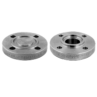
The above is the basic description of the flange faces. When choosing the flange installed with the pump, it is recommended to consult with professionals before select it.
PTCXPUMP sealless magnetic drive pump provides standard flange specifications(ANSI,JIS,DIN) for easy pipeline connection. It can adjust screw hole position to avoid leakage of inlet and outlet.Best Solution For Chemical Transfer 》 PTCXPUMP Sealless Magnetic Drive Pump
When the pump is connected to the pipeline, we generally use flanges, unions or hoses for connection. For the application of medium and large pumps, we often use flanges as the main connection method. Flange refers to the disc-shaped parts used to connect pipes, containers, or fix the shafts. Usually, there are screws and threaded structures to fix them. Flanges are generally used in pairs, the most common in pipeline engineering. The typical connection consist of flanges, gaskets and screws. Gaskets are added to the two flanges and tightly fixed with screws. Widely used in chemical industry, petrochemical industry, firefighting, drainage or water treatment application for liquid transfer solution.
There are countless types of flanges. The commonly used materials are carbon steel, stainless steel, alloy steel, etc. In addition, the thickness, the number of screw holes, and the diameter of the flange need to be selected according to the operation requirements.
The common types of flanges can be divided into Slip On Flange(SO), Weld Neck Flange(WN), Threaded Flange(THDF), Lap Joint Flange(LJ), Socket Weld flange(SW), Blind Flange(BL), and other special types(Specialty Flange), the following basically introduces several main flange types.
Slip On Flange(SO)
A fairly common type with lower installation costs and lower requirements for precise pipe cutting. The steel pipe, pipe fittings are inserted into the inner hole of flange and connected to the pipe through a fillet weld at the flange top and bottom. Since the flange hole is larger than the pipe diameter, it usually requires more welding action than other flanges, so it can effectively prevent leakage. Compared with weld neck flange, it is only suitable for low and medium pressure applications due to the lower neck height.
Weld Neck Flange(WN)
It is a flange that is butt welded to the pipe or fitting, and its installation cost is higher. In contrast to the slip on flange, the distance between the welding joint and the joint surface is large, and the joint surface will not be deformed by the welding temperature. Weld neck flanges are not easily deformed and have high sealing properties, making them suitable for high temperature and high pressure, even for pipelines that transport flammable and toxic fluids.
Threaded Flange(THDF)
The inner hole of the flange is processed into a screw thread and connected with a threaded pipe, which belongs to a non-welded flange. The main feature is easy installation, disassembly and maintenance. However, considering the characteristics of thread structure, it is strongly influenced by the environment, and the temperature in the threaded pipe fluctuates greatly, so it is not suitable for high temperature and high pressure applications.
Lap Joint Flange(LJ)
It consists of two parts, the Stub End and the Backing Flange. The flange is placed on the stub end, and the stub end is butt welded to the pipe joint. The flange can move on the pipe joint. It is mainly used for pipe systems that need to be disassembled frequently for inspection and maintenance. The flanging of the stub end is the sealing surface, and the flange is used to clamp the end of the pipe and the stub end. Because flanging stub end can isolate the flange from medium, it is suitable for conveying corrosive fluids.
Socket Weld flange(SW)
The inner hole of flanges has a socket and is connected by inserting the pipe into the socket and fillet welding around the top. Usually used in smaller, high-pressure pipelines, but not for highly corrosive fluids.
Blind Flange(BL)
It is a flange without a hole in the middle for closing the end of the pipe, with mounting holes around the perimeter and the gasket sealing rings are machined into the mating surface. The function is the same as the head and the cap, and the blind flange is fixed with screws for easy disassembly.
PTCXPUMP sealless magnetic drive pump provides standard flange specifications(ANSI,JIS,DIN) for easy pipeline connection. It can adjust screw hole position to avoid leakage of inlet and outlet.
Best Solution For Chemical Transfer – PTCXPUMP Sealless Magnetic Drive Pump
Why do you need to use explosion-proof motors? Explosion-proof motors are mainly used in harsh environments. In the process environment, the air will contain flammable substances, including gas or dust. When a specific concentration is reached, once there is an ignition source, it will cause fire or explosion. Explosion-proof motors can prevent explosions by isolating thermal energy from contact with combustibles and controlling the operating temperature of the motor. When the commonly used sealless magnetic drive pump or centrifugal pump is equipped with an explosion-proof motor, we can call it explosion-proof magnetic pump or explosion-proof centrifugal pump. The explosion-proof motor is selected according to the environment and process. The following will introduce the markings and classifications of explosion-proof equipments.
Explosion-proof marking refers to the mark used to describe the explosion-proof grade, temperature group, protection type and applicable environment of explosion-proof electrical equipment.
The common explosion-proof classification standards mainly include IECEx and ATEX, as well as NEC and CEC.
IECEx: An international, worldwide explosion-proof standard defined by the International Electrotechnical Commission (IEC). An international certification system helps reduce testing and certification costs for manufacturers, allowing the unified standards to be applied in different countries. IECEx is also stricter than ATEX in the certification process.
ATEX: Basically similar to IECEx, but only used in European countries.
NEC: For use in the United States only.
CEC: For use in Canada only.
The following describes the meaning of each indication of the two major standards, IECEx and ATEX.
IECEx ex.

ATEX ex.
Whether it is temperature, gas or dust, the environment where the equipment is located, etc., there are many factors that determine the specifications of the motor. After the above introduction, when selecting an explosion-proof motor, the meaning of these specifications can be more clearly understood.
Motor is an indispensable part of the industrial automation and one of the most common electrical equipment in life. It is widely used in various electrical appliances, ranging from washing machines and fans in daily life; For industrial applications, pumping, machinery industry and fluid transfer, etc. Motors are also indispensable when pumps are used. Therefore, it is very important to understand and choose a suitable motor. The following describes the differences between normal motors, inverter duty motors and explosion-proof motors.
Normal Motors
There are many types of motors, according to the type of input power, they can be divided into DC motors, AC motors, etc. DC motors can be further subdivided into brushed DC motor, brushless DC motor(BLDC motor); AC motor includes induction motor and synchronous motor. In brief, DC motor controls the rotational speed through voltage, which is easy to control, but not suitable for high temperature and flammable operating environments. The AC motor controls the rotational speed through the frequency of the alternating current, so compared with the DC motor, it is not easy to control the speed, while it can be used in a high temperature and flammable operating environments.
Inverter Duty Motors
A variable frequency drive (VFD) (a.k.a Inverter) is used to change the frequency of the alternating current, by changing and controlling the speed and torque of the AC motor. Therefore, "variable frequency" refers to the way of driving the AC motor. It can be started and adjusted frequently without maintaining full-speed operation and maximum power. When the motor speed is reduced, the output horsepower will also decrease, thereby achieving high efficiency and energy saving. The system control is also more stable than the normal traditional motor.
Explosion-Proof Motors
Mainly used in operating environments where flammable substances exist, such as coal mining, natural gas industry, petrochemical and chemical industries, etc. With the hard explosion-proof shell, it can sustain the explosion pressure inside the motor, and also can isolate the heat from the inflammable materials, so as to avoid the danger of fire or explosion.
According to the explosion-proof form, it can be roughly divided into flameproof motor (symbol d), intrinsic safety motor (symbol i), increased safety motor (symbol e), positive pressure explosion-proof motor (symbol p), non-sparking motor (symbol n), and dust ignition proof motor, etc., depending on the protection level, each has its features and functions.
With a brief understanding of the differences between these motors, I believe it becomes easier to choose the right motor for your needs.
Best Solution For Chemical Transfer – PTCXPUMP Sealless Magnetic Drive Pump